Pin 1 - Ignition positive
Pin 2 -
Pin 3 - Data Tacho / MUX network Late generation
Pin 4 - Chassis ground
Pin 5 - Chassis ground
Pin 6 - Data Climate control/CAN High ('IS' Late generation)
Pin 7 - K Line Data Engine management / Automatic gearbox management
Pin 8 - Cooling fan control information / MUX network Late generation
Pin 9 - Charge information
Pin 10 -
Pin 11 - Data BSI
Pin 12 - K Line Data ABS/ESP/GEP/Suspension control
Pin 13 - Data Air Bag/Headlight control
Pin 14 - CAN Low('IS'.. Late generation)
Pin 15 - Data Engine management
Pin 16 - Battery positive
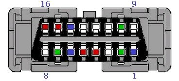
The OPEL/Vauxhall Vectra should use the CAN BUS to exchange information between the various components. I wonder how the pin are placed on the actual connector, since it seems a bit different. We will have to attach probably to pins 6 and 14 to get access to the bus.

No comments:
Post a Comment