Saturday, December 12, 2009

Ping? Pong!

Hi all!

As you may remind (maybe not ;-) ) we had not so much success in our can-bus experiments. The Vectra bus details are near totally unknown (at least for us), and we can't ever debug our interface, and this sense of vagueness is very frustrating. We felt like a blind man in a sandstorm.

To minimize this effect we try to build a cornerstone, developing a working can-bus scanner, replicating our interface. But the results are describend in the last post. So we have intensified our efforts in this direction. And finally...

IT WORKS! :D


We have successfully connected two PIC18F4682 with a Can-bus, at a speed of 95kbit, which should be the speed of MScan of Vectra. We checked communications, message type, payload etc. All work now. We implemented a progressive encoded (well... take it easy...) message passing to check that the messages we were exchanging were really the ones we espected.

This step should give us a good starting point for interfacing: the receive() function works for sure, now we can do a functional sniff routine.

The quest now is: will we find the right bus speed?
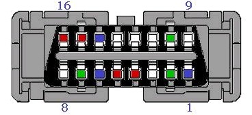
Friday, November 27, 2009

After our last unsuccessful try to communicate with the Vectra CANBUS, we decide to take a step backward and ensure that we were doing things the right way. In particular, we were interested in knowing if the CANBUS chip was connected right and if the logic of the program was correct.
To test this we got another breadboard and tried to replicate our current circuit so that we would eventually have two CANBUS connected PICs that could talk together, confirming we were doing things right.
So this was the breadboard at the actual state of the project:
And this one is the new breadboard with the essential part of the circuit cloned:
We went on and attached the programmer to the new breadboard but it did not work. The programmer simply could not find the PIC. We feared we had burned some chip due to incorrect power connections and proceeded checking differences with the original circuit. There weren't any.
To check whether we had really burnt the chip, we put it in the original breadboard and worked as expected. After putting it back in the new breadboard we could not figure what was wrong and spent really a lot of time trying to iron this out. In the end, we removed every chip and connection from the board and put them back in a different position paying extra attention to any connection. This time the chip worked and could be finally programmed and run.
We proceeded to connect the boards and wrote a different program on each chip, one that transmitted one message and the other that printed to the serial port the messages received (only the original breadboard has serial port chips). It didn't work. We tried to change the programs but it was already too late and we had to stop there.
Next time we hope to have the two boards communicate via CANBUS.

Friday, October 30, 2009

BZZZAAP!!!

Hi ALL!! After a long, long time we are back! Holidays, work and H1N1 (well... not really, only ordinary flu :-) ) have delayed our serious work, but yesterday we restarted it. As you can see...

some ruffled wires were connected to the EODB port. This is not really the first time that we interface our circuit to the car, but the last try was a failure. After some changes (both in code and wires) we do it again.

Results:

not many, really. We detect correctly the start of trasmission on the bus: when we turn on the ignition switch our circuit start receiving packets. Unfortunately the PIC module signals "overflow" status on CAN receiver, so we haven't received nothing meaningful. We hope we have guessed right the bus transmission speed, but we have to investigate further.
We did some exeriments on receiving packets (echoing on serial port, binking led...) to locate the problem, but the available time runs out quickly. But there will be the second round. :-)

Looking in the photos (sorry about the quality, the pictures are taken with a cellular phone in the dark, so noise is clearly visible) you can see the wires connecting EOBD in the hole above the shift lever and the circuit. The grey cable (a chunk of CAT5) on the right is connected to the serial port of laptop (not shown), you can see it a little better on the above photo. The dark box with leds turned on is PICkit2, the PIC programmer (also connected to laptop). We were doing real-time debugging of firmware :-)

That's all folks! We will be back as soon as possible, to continue this first part of the project. Stay tuned!

Tuesday, June 23, 2009

Playing a bit with SocketCan and its utilities

This time I had a better look at the SocketCan utilities that I mentioned in a previous post. As I have already told, you can get and install them with these commands:
svn checkout http://svn.berlios.de/svnroot/repos/socketcan/trunk canbus
cd canbus/can-utils/
make
make install

And you will end up with lots of new programs under /usr/local/bin:
asc2log canbusload candump cangen
canlogserver canplayer cansend cansniffer
isotpdump isotprecv isotpsend isotpsniffer
isotptun log2long slcand slcanpty vcan

To see how canbus works, I tried to setup a virtual can bus with these commands:

modprobe vcan can-raw
ip link add dev vcan-test type vcan
ifconfig vcan-test up

These basically creates a canbus named vcan-test and set the interface up.
Then I opened two terminals and ran the command candump on one terminal and the command cansend on the other terminal. These are the outputs:
# cansend vcan-test 5A1#11.2233.44556677.88
# cansend vcan-test 5A1#11.2233.44556677
# cansend vcan-test 1F334455#1122334455667788

# candump vcan-test
vcan-test 5A1 [8] 11 22 33 44 55 66 77 88
vcan-test 5A1 [7] 11 22 33 44 55 66 77
vcan-test 1F334455 [8] 11 22 33 44 55 66 77 88

That are the message id and the data. The number between the brackets is the data length and the last case is with an extended id.

This could also be the text format used by the slcan driver to communicate via serial port.
I have tried to use slcanpty to attach the vcan-test interface to a pseudo terminal but without success so far. I will have to try again soon as it could be the way to gather the data on the Linux machine without writing an additional custom layer.

Thursday, June 18, 2009

Two interesting CANBUS projects and some links

This CANalyser tool is pretty similar to what we want to do at the moment and is built with very similar chips. The project seems a bit outdated but the information is still very useful.
The tool is composed by a PIC microcontroller PIC18F458, and a MCP2551 CAN transceiver. The main features are listen to the CAN bus in active or passive mode and forward data to the serial port to the PC and send data to the CANBUS. This is exactly what we need now.
Digging further in the web pages I discover that they have built a real-time kernel to run their software on the PIC. There is a company behind this (Pragmatec) but they have released the sources under a GPL license. The website of the os is at PICOS18
There is a new version of the pages here but the page about the CANalyser tool is the same.

Another very similar tool is CAN2PIC. This one uses
PIC18F248 and MCP2551 CAN.
You can find there all the schematics of the circuit used and also all the software! So this page should provide all we need to get started and running very fast!

There are some other interesting links I found tonight:
  • GNUPIC: a small directory site with information on PIC programming with GNU/Linux
  • Another very good CANBUS learning page at CERN (yes they used it in LHC)
  • PICMICRO WebRing: A collection of websites about the Microchip PIC microcontroller and related projects

Sunday, June 14, 2009

Canbus programming under linux: SocketCAN

Well the good news is that someone already did the hard part for us!
The Linux kernel includes since several versions the support to the can protocol and provides what seems to be a very easy interface to it. It's called SocketCAN and it is modeled after the standard unix socket API.
The project page is at BerliOS and hosts the kernel patches (not needed anymore as it is included in mainstream) and some user space tools that I just downloaded and installed without a glitch. You can get them by accessing the project subversion repository with this command: svn checkout http://svn.berlios.de/svnroot/repos/socketcan/trunk canbus

More info on what is and how to use SocketCan can be found in the linux kernel documentation directory (available on the web here)

As for the device drivers, SocketCAN supports a few drivers alreay, two of which are particularly interesting: vcan and slcan. Vcan is a virtual CAN interface driver and is there for testing when there is no hardware available. This will be probably the first to try once I realize how the user space utilities work. The slcan driver is "For a bunch of CAN adaptors that are attached via a serial line ASCII protocol (for serial / USB adaptors)" and should match exactly what we are trying to do. I just wonder what is the data format the slcan drivers expects to receive from the serial port. I have only found a strange document here so far but the semantic is not clear to me and I will have to investigate this further.

Saturday, June 6, 2009

Getting the tools part 2: a matter of levels

After choosing the main component of the project in a previous post, we also have to connect it :-)
On one side we have the CANbus connector, on the other (probably) a PC used to understand what informations are going up and down on the CAN. Unfortunately we can't connect PC directly to CANbus, due the lacking of a suitable peripheral on PC. So we choosed a PIC18F4682 to do the raw job. So is it all done?

NO

Connecting directly CAN, PIC and PC probably will result in a big roast, with nothing to eat :( . So we will use these two tiny chips, ready on the breadboard:
Their work is to convert voltage levels in a suitable way.


MAX232CPE from Maxim is a level converter for RS232 (serial) protocol. It converts +12/-12 signals from PC serial port to +5v accepted from PIC, and do the opposite job on the other direction. To do this it needs some condensers, not yet installed, to produce the necessary voltages, cause it's main voltage is only +5V.


MCP2551 from Microchip converts CANbus signals (what is the voltage on Vectra CAN bus? we still don't know...) to PIC level. We HOPE that this interface chip will do the job, cause the real implementation of CANbus on Vectra (voltage, speed, protocols, messages...) is still totally unknown. MCP main voltage is also +5V.


On the left side of the first photo you can see a bunch of components and wires. This will be our 5V power plant. LM7805 with 2 condensers will give power to all our chips and components we will use in this project. Now it is time to connect everything: stay tuned!

Wednesday, May 27, 2009

Can Bus specifications

The official (I think) CANBUS specification can be found at CIA, that stands for Can In Automation. There are both base and extended protocol. They seems to be very clear and intuitive and I think they will be very helpful as soon as we start coding some CAN sniffer or similar. I have to start thinking about how big the sniffed data will be and where to store that so that we can study it easily. Maybe the only choice for this is a database (for which I guess mysql would do pretty well).
We'll see soon. Coding time is approaching!

Saturday, May 23, 2009

Great Can Bus hacked page on a Saab

I have found this really interesting page here. It is from a guy who reverse engineered the instrument bus on a Saab. This bus is called I-bus and is based on CAN bus. He gives a lot of information on how he did it, starting from locating the connector, attaching to the bus and interfacing with the PC, along with the tools he used.
It is very similar to what we would like to do and thus we can get lots of advices from it. There are important differences though. He bought ready-to-use CANBUS connectors while we are trying to do it by ourselves. Well actually he says that he tried to do it himself but could not make it work so he switched to commercial products, but he does not give much information on how he tried and what did not work.
The other big difference is that as he is using commercial products, he also has access to programs on Windows platform that can decode bus messages and help during reverse engineering. We won't have these programs because of our do-it-yourself choice and also because we plan to use Linux to get access to the bus by using a serial interface. This is clearly much harder to do but I hope it is not so hard that we will eventually be forced to switch to commercial products.
We will also have to develop our own programs on the Linux platform, but this should not be a big problem. We have to look around for already existing projects to see if we can reuse some code.

This page also gives us a real example of what the message on CANBUS looks like and how they are used by the car. He also explains how the information is spread on multiple messages as for the case of the radio display. Definitely an helpful page!

Wednesday, May 20, 2009

Can Bus Topology in the Vectra

I have found a very interesting document here: it is about the testing architecture developed at Opel for the Vectra. They call it Hardware-in-the-loop (HIL) simulation. Basically, due to the increasing number of ECU (Electronic Control Unit), they say that testing has become very difficult and thus they developed a new test methodology based on the dSpace product that gives the possibility to do automated testing of the components interaction and to reliably reproduce the failing tests.
Pretty interesting stuff but how does this relate to our adventure? It does because the document gives also some information about the can bus of the Vectra and has a picture of its topology. There are three busses in the car: low-speed, mid-speed and high-speed. This is the list of the ECUs for each bus:

  • High-speed: Steering column integrated module, Yaw rate sensor, Electronic stability program, electro-hydraulic power steering, Automatic headlamp control, Automatic transmission control, Engine ECU
  • Low-speed: Steering column integrated module, Body control module, Driver door module, Instrument panel cluster, Rear electronics central module, Shift lever module, Displays, Auxiliary heater, Passenger door module, Driver seat module, Parking assistant, Airbag, Sun roof module, Underhood electronics, Display module
  • Mid-speed: Display module, Audio system, Car phone, CD changer, Electronic climate control, Global Positioning System, Navigation control unit, Telematics system

From this picture and list, we can deduce that two modules are acting as gateways between the different busses. They are the Display Module and Steering column integrated module. What they are exactly and what is their function, we don't know yet. I start now to wonder to which bus the can bus pins on the EOBD connector are attached. We will need more information on this and probably also to measure the speed of the canbus we have access to.

Friday, May 15, 2009

About CAN BUS

Here I have found a good introduction to the CAN bus.
It is a link level protocol, similar to ethernet, with CDMA (Collision Detect, Multiple Access) policy.
Every CAN bus peripheral can receive and send data on the same bus and has the capabilities to recognize where someone else is using the bus at the same time. A priority mechanism ensures that in this case only one transmission is completed.
Unlike ethernet, this protocol is content oriented, that means the each message does not have destination and source fields, but just an identifier that specifies the meaning of the data associated to the message. The meaning of the identifier is not specified in this standard as it is choosen by higher level applications.

Each message consists of an identifier, some flags and crc and the payload.
The identifier is 11bit wide in CAN bus version 2.0A and 29bits wide in version 2.0B

There are four different message types:
  • Data frame: a frame containing node data for transmission
  • Remote frame: a frame requesting the transmission of a specific identifier
  • Error frame: a frame transmitted by any node detecting an error
  • Overload frame: a frame to inject a delay between data and/or remote frames
The arbitration on the bus is based on the identifier. As the bus is AND wired, each time two components send a signal on the bus, the result on the bus is the logical AND between the two signals. This means that when collision happen, only one of the identifiers of the messages gets trasmitted to the bus (the one with most zeros); the transmitter can simultaneously read what is on the bus and if the identifier coincides they proceed to transmit the complete message.

This info on Wikipedia will probably be very useful to get data structures written in C or any other language I might choose for this adventure.

Wednesday, May 13, 2009

Getting the tools: part 1

After some time spent to think of what tools we need in this adventure, now the heart of the project has arrived:


This beauty is a PIC 18F4682 from Microchip. Among many other features, it spots:
  • Enhanced CAN controller on board ( CAN version 2.0B up to 1Mbps)
  • 1 EUSART ( for RS232 )
  • 10 MIPS @ 40Mhz
This is another voyeuristic closeup of the microcontroller:
The microcontroller will be our interface to CAN bus, where we will try to listen communications on the bus and to talk with the other peripherals. It is not possible to interface directly a PC for electric problems (signals are transmitted on the bus by differential voltage) and protocol reasons (need of a dedicated hardware to understand message on the lines that normal PC doesn't have on board). Unfortunately this is not the only device that we need for the project. More has to come.

Stay tuned!

Monday, May 11, 2009

EOBD Connector Pin Layout

According to the info found on this page this should be the pin layout for the EOBD connector:

Pin 1 - Ignition positive
Pin 2 -
Pin 3 - Data Tacho / MUX network Late generation
Pin 4 - Chassis ground
Pin 5 - Chassis ground
Pin 6 - Data Climate control/CAN High ('IS' Late generation)
Pin 7 - K Line Data Engine management / Automatic gearbox management
Pin 8 - Cooling fan control information / MUX network Late generation
Pin 9 - Charge information
Pin 10 -
Pin 11 - Data BSI
Pin 12 - K Line Data ABS/ESP/GEP/Suspension control
Pin 13 - Data Air Bag/Headlight control
Pin 14 - CAN Low('IS'.. Late generation)
Pin 15 - Data Engine management
Pin 16 - Battery positive


The OPEL/Vauxhall Vectra should use the CAN BUS to exchange information between the various components. I wonder how the pin are placed on the actual connector, since it seems a bit different. We will have to attach probably to pins 6 and 14 to get access to the bus.

EOBD Connector Location


As I promised, here is the photo of the exact location of the connector on the Vectra. It is very easy accessible and I hope it will provide a very easy access to the car bus system.

Tuesday, May 5, 2009

EOBD on board diagnostic connector on the Vectra

Seems like my 2002 Vauxhall/OPEL Vectra supports the EOBD connector. I have found it near the gear shift lever and I'm now pretty sure about it thanks to this image:

found with Google Images. I'll post a picture of the exact location as soon as I can download photos from my mobile or get a decent camera.
This connector should provide access to all the internal diagnostic informations from the car like tire pressure, engine parameters, temperatures and more.
I have found some more info on it on Wikipedia. Seems like it's a standard for European vehicles since 2001 and should also include the CANBUS interface I'm interested in.
Now that I think about it, it should also be present on the other Vauxhall our family owns. I have to check this sooner or later!